Wiring Configuration For 7Way Vehicle And Trailer Connectors
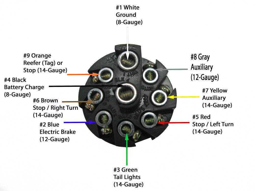
The minimum suggested wire size for a 7-way trailer plug is 16 gauge for the turn signals, brake lights, reverse lights, and running light wires. The suggested minimum for the ground, brake power, and battery hot lead wires is 12 gauge. Shop Custom Wiring Wiring a Trailer with a 7-Way: Step by Step
Standard Wiring Diagram For 7 Pin Trailer Plug Adapter Wiring Diagrams Megan Daily
In this video, Reece takes us through wiring up a 7 Pin Plug.Outback Equipment sells a wide range of 4x4, caravan, camping, marine and electrical accessories.
7 Pin Trailer Wiring Diagram With Brakes And Battery Wire A Trailer Wire A Trailer
What is a 7-Pin Trailer Plug? A 7-pin trailer plug is a crucial component for connecting a trailer to a vehicle. It provides power for the trailer's lights, brakes, and other electrical systems. Without this plug, towing a trailer safely and legally would be impossible. Contents What is a 7-Pin Trailer Plug?
Standard 7 Pin Trailer Plug Wiring Diagram
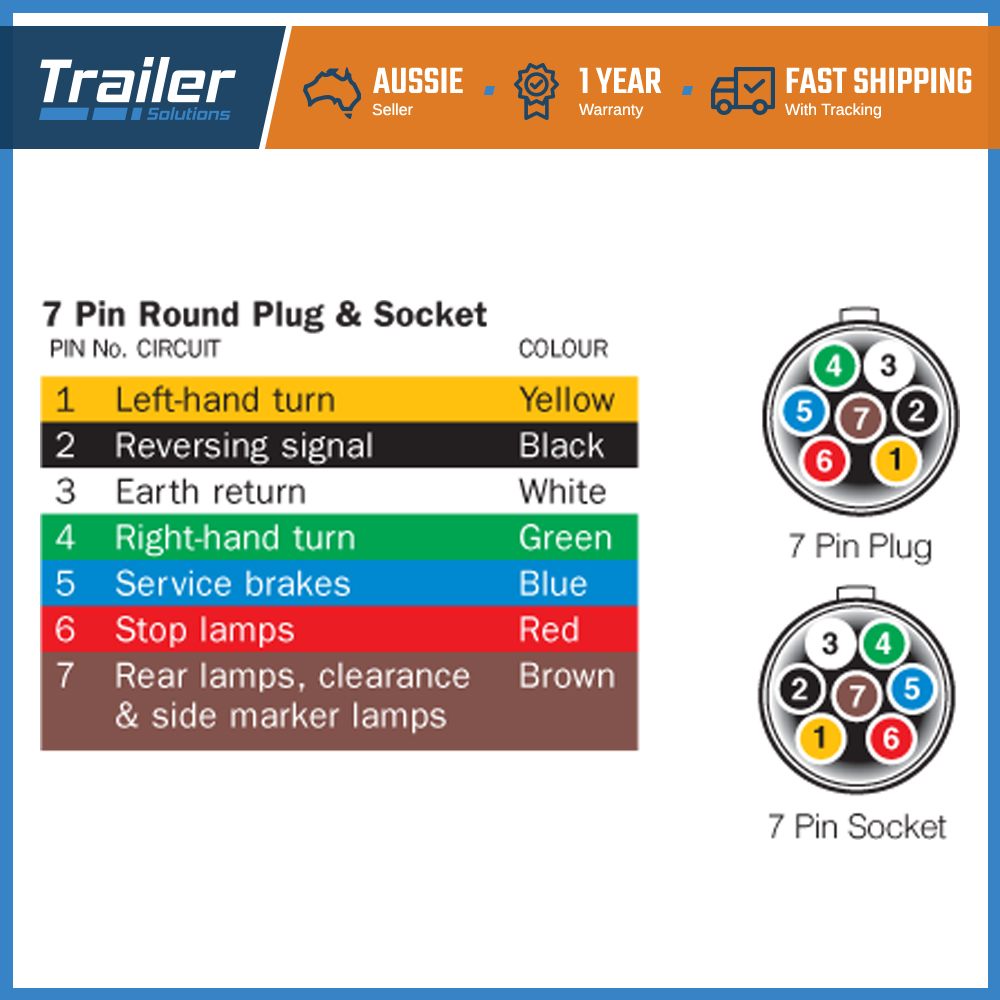
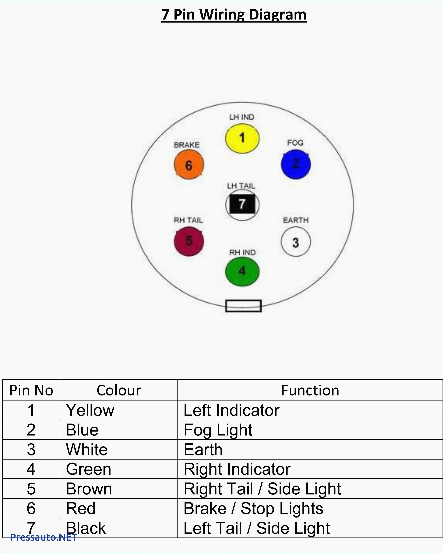
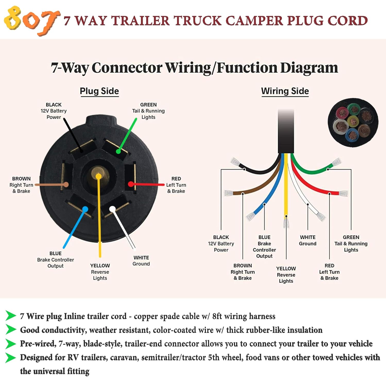
A 7 pin trailer wiring diagram is a schematic that shows the pinout and function of each wire in a 7-way round trailer connector. The standard 7-pin connector contains the following wires and functions: The diagram uses color coding and labeling to identify the purpose of each pin's wire. It traces the path of the wires from the connector.

7 Pin Trailer Plug Wiring Diagram Usa Wiring Harness Diagram
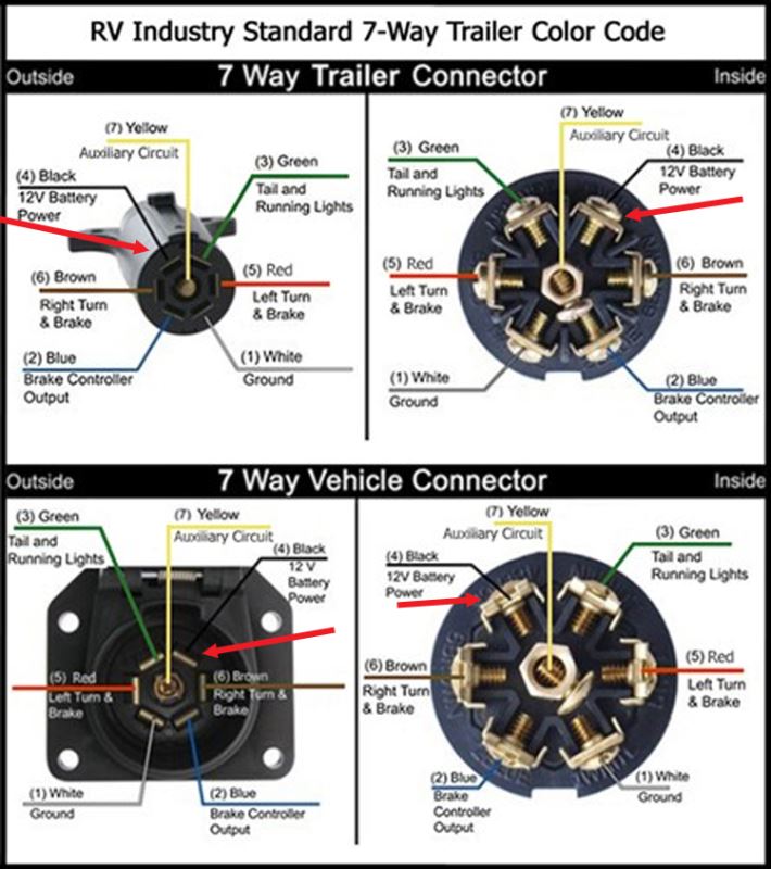
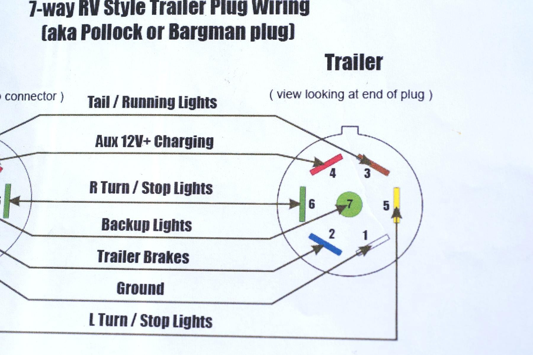
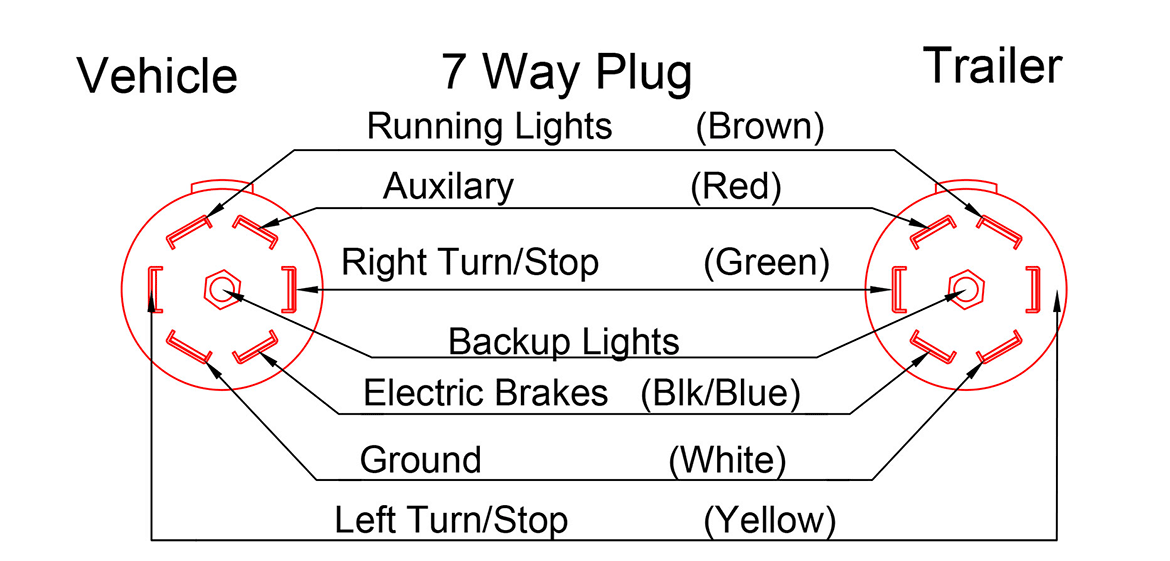
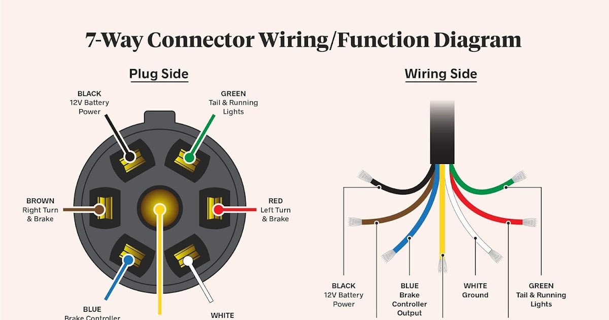
7 Way Plug Wiring Diagram Standard Wiring* This is the most common (Standard) wiring scheme for RV Plugs and the one used by major auto manufacturers today. * Always test wires for function and wire accordingly. This wiring scheme is for reference only. copyright © 2001, Country Trailer Sales All Rights Reserved
7 Pin Trailer Connector Diagram 7 Pin Trailer Plug Wiring Diagram Database Wiring
Est. 1951. Current Version J560_202002. Scope 7-pin 12V trailer connectors. Regionality North America. The standard SAE J560 for trailer connectors was originally issued in 1951 to create a standard in the commercial vehicle industry for the electrical wiring between heavy-duty truck and trailer. The latest revision is from 2020.
Trailer Wire Diagram 7 Pin
Like a T-connector, an original equipment wiring harness plugs into the USCAR socket without any cutting, splicing or soldering required, and it provides a standard trailer wiring output, such as a 4-way flat or 7-way RV blade. Learn more about USCAR wiring Option B: Taillight Converter Splice-in Wiring
Wiring Diagram For 7 Pin Trailer Plug
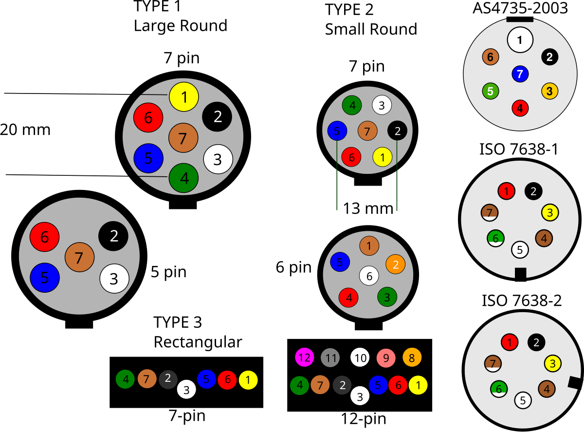
Various connectors are available from four to seven pins that allow for the transfer of power for the lighting as well as auxiliary functions such as an electric trailer brake controller, backup lights, or a 12V power supply for a winch or interior trailer lights.
7 Pin Trailer Plug Wiring Diagram Usa
The 7 pin trailer plug is a crucial component in the towing system of a vehicle. It allows for the transmission of electrical signals between the towing vehicle and the trailer, enabling various functions such as turning indicators, brake lights, and power supply to be synchronized.
7 pole trailer plug wiring
Physical design according to standard ISO 7638-2. [4] [6] [7] This connector is intended to be used for 12V ABS and EBS on heavy duty trailers. Identified by key tab on outer ring between pin 3 and 4. The following supplementary information exists for the connector: ^ a b CAN bus communication according to ISO 11992.
Trailer Wiring Diagram 7 Pin Wiring Diagram
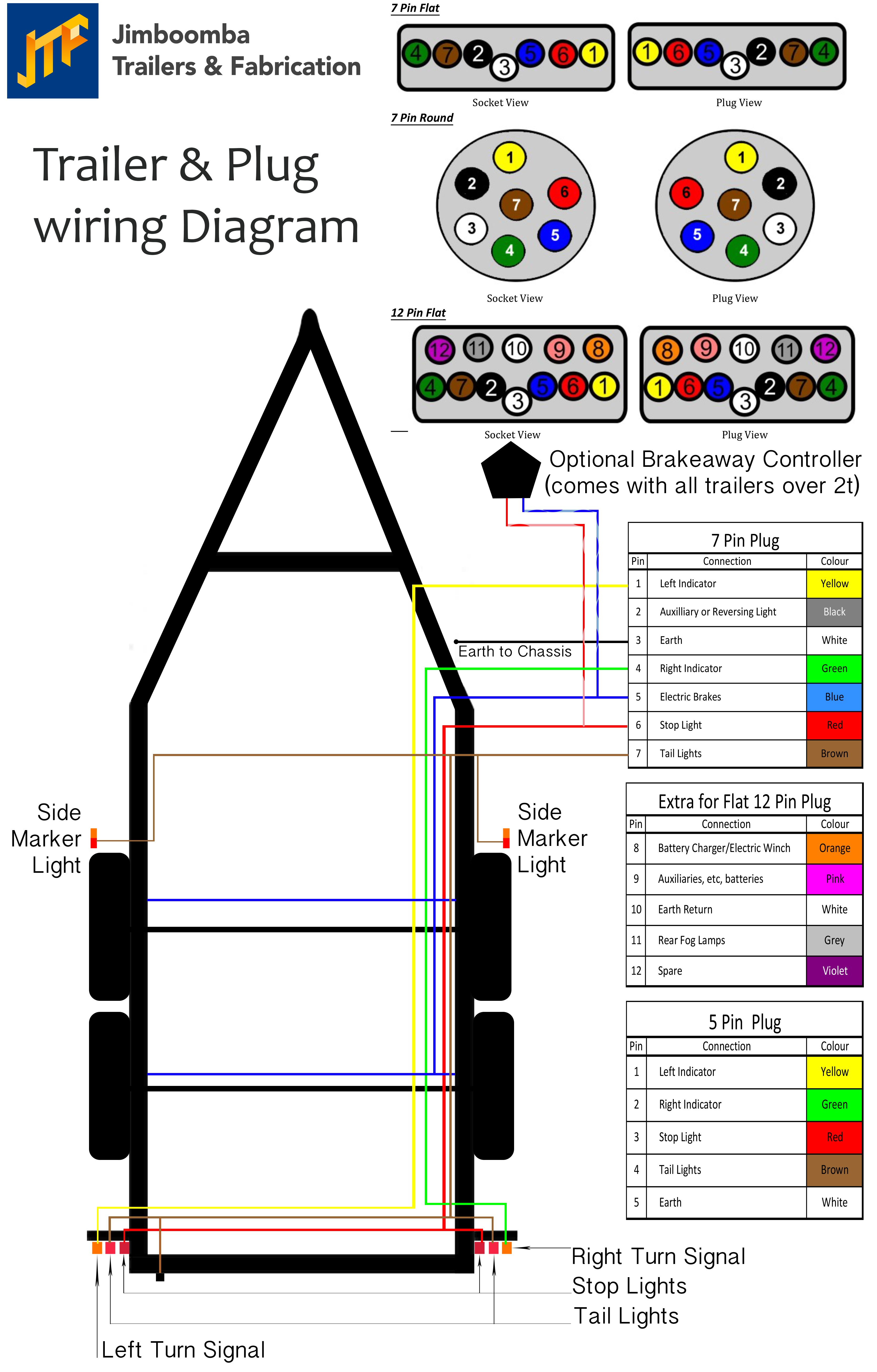
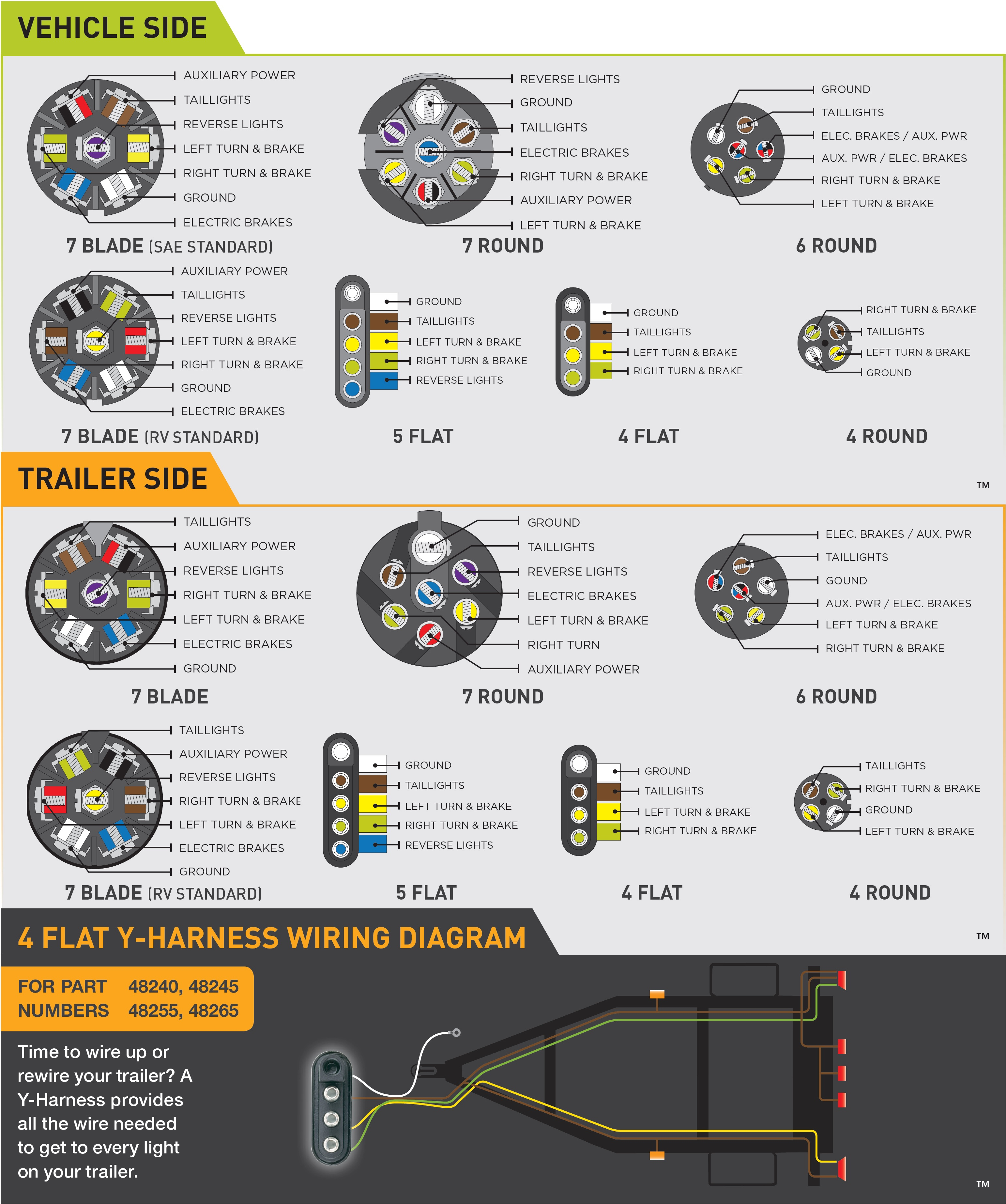
The 7 pin trailer wiring diagram for each trailer type (standard, RV, heavy duty) Descriptions and illustrations of where and how to properly connect all wiring Table of Contents show 7 Pin Trailer Wiring - Color Codes There are seven different electrical wires that connect and sync the 7 pin trailer connector with your vehicle.
7 Pin Trailer Plug Wiring Diagram Flat Wiring Diagram
The most common type of trailer plug is the 7-pin round plug, which has seven connectors for various functions. This includes the ground wire, left turn and brake lights, right turn and brake lights, tail lights, electric brakes, auxiliary power, and backup lights.

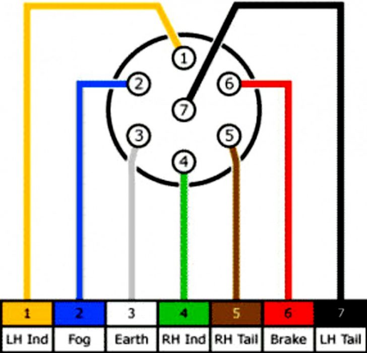
Standard 7 Pin Trailer Plug Wiring Diagram Uk
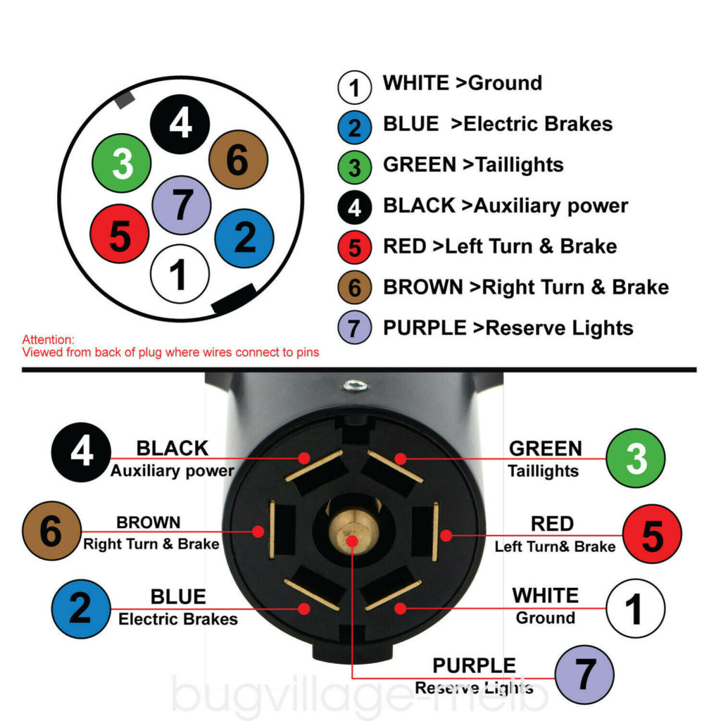
The 7 pins on the plug deliver power/signaling to 7 different actions/connections on the trailer connector. And yes, these do include the trailer lights. Let's take a look at the wires of each of the 7 pins of one RV 7-pin trailer plug, in particular, to see what function is powered by each wire leading to those pins.

7 Pin Connector Trailer Wiring
There are two key components that make up these systems: The 7-pin connectors and wiring mounted on both the vehicle and trailer. The connecting wires that join to circuits to carry signals and power. There are two common configurations of 7-way connectors: Standard: The most widely used. Reverse Pin-Out: A configuration with opposing pin.
Wiring For 7 Pin Trailer Plug
The 7-Way Trailer Plug is around 2″ diameter connector that allows an additional pin for an auxiliary 12-volt power or backup lights. It is usually used for towing heavy-duty cargo trailers, aluminum trailers, dump trailers, utility / landscape trailers, equipment trailers, open car haulers and enclosed car haulers.
Wiring A 7 Pin Trailer
There is a standard method of wiring a 7-pin trailer connector. If you don't follow this your trailer (or tow vehicle) can't be used with any other implement.
- Rodaballo A La Sal
- Feliz Cumpleaños Picantes Para Hombres
- Fotos Antiguas De Cañete De Las Torres
- Dibujo De Un Elefante Para Colorear
- Frases Motivadoras Ciclismo
- Jaulas Trampa Para Gatos
- Croquetas De Gambas Peladas Congeladas
- Ejercicios De Rehabilitación Vestibular
- Bodas En Otoño Invitadas
- Jayson Tatum Wallpapers